Motor Mount Tech Session with Paul Horton’s Welder Series
There are many factors that affect the location of the motor in a hot rod or custom car or truck chassis: Plan ahead.
In no particular order, the tech session produced these points to consider when mounting a motor in a hot rod or custom car or truck project:
- The frame should be at ride height and rake when mounting the motor and transmission.
- On Mustang II suspended chassis, have the rack mounted. It is often higher than the cross-member and may interfere with the oil pan.
- The carburetor does not have to be level, but try to be close.
- Pinion angle (up at the front) should be the same as the crank/transmission angle (down at the rear) and the u-joint angle should be 3 degrees or less.
- Crank center-line does not have to be in-line with the pinion when viewed from above.
- Crank/transmission line does not have to parallel with the frame center-line when viewed from above. The transmission is in the center of the frame (located because of the stock x-member passage) and the front of the motor is offset to one side (usually the passenger) for clearance. The 3 degree u-joint angle is the determining factor, as above (per Inland Empire Driveline – Armando)
- Have motor/transmission on-hand to know all of the clearances required.
- Have the radiator mounted. It often can be moved, but sometimes must be in a specific location (and sometimes mounted at an angle).
- Know what fan will be used so clearance can be planned.
- Have the body mounted.
- Have the firewall or be prepared to custom make it.
- The floor might have to be modified for trans clearance.
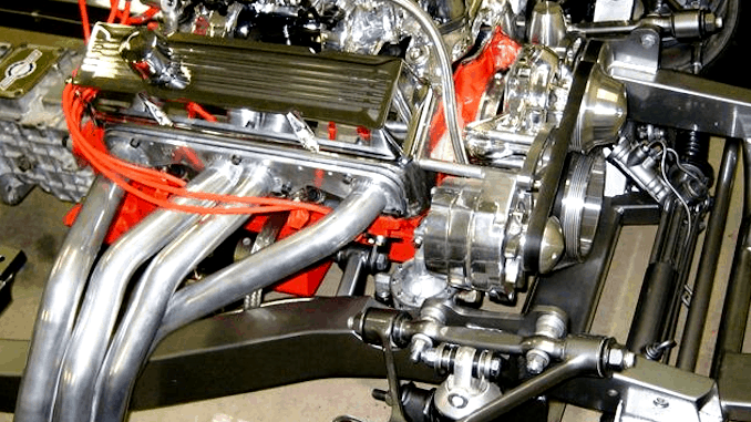
- Headers and steering will want to occupy the same space. Consider this when positioning the motor.
- Rubber OEM mounts absorb more engine vibrations than urethane 4-bar bushings. The urethane 4-link bushing mounts usually look more “high-tech”. Use the mounts that suit the style of your project rather than worrying about the amount of vibration transfer. It won’t be that much different.
- Plan for hood clearance.
- Have the water pump installed so clearance can be planned.
Download the Power Train Setup Tech Sheet (PDF from Inland Empire Driveline) — “This booklet covers the placement of power train components in the chassis. The engine/transmission, the third member and the drive shaft must be installed to work in harmony if drive-ability is your goal.”
Download the Power Train Setup Guide (PDF from Inland Empire Driveline) — “Having a little information at the beginning of your street rod project can make setting up power train angles one of the simplest steps in the building process.”


