
Problem: Driveline / driveshaft vibration. Driveline geometry incorrect (wrong engine/pinion angle).
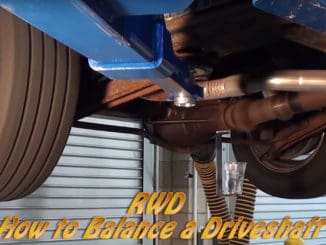
Driveshaft Harmonics
Jim Clark, Hot Rod M.D. — The process that can be used to address a condition called driveshaft/universal joint cancellation, often referred to as adjusting pinion angle.
This process can be used to eliminate the vibration and premature wear caused by improper orientation and phasing of the drive-shaft.
This condition is caused because every U-joint that operates at an angle creates a vibration. It creates that vibration because the U-joint cross rotates with the shaft in a circular motion while also moving from front to rear. That rocking back and forth motion as it rotates causes the cross in the U-joint to accelerate and decelerate.
If you could view this as rotating around the face of a clock with the cross rotating in a counterclockwise motion it would show the U-joint when at a horizontal position (3 to 9 o’clock) as traveling in a circular motion.
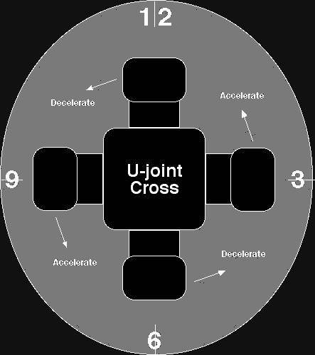
As the yoke arm at 3 o’clock travels counterclockwise towards 12 o’clock and tips to the rear of the vehicle it accelerates.
Then decelerates as it continues counterclockwise towards 9 o’clock as it rocks forward again returning to center. Now again accelerates as it continues rotating counterclockwise from 9 o’clock to 6 o’clock and rocking towards the front of the vehicle.
Finally completing one rotation as it travels counterclockwise from 6 o’clock to 3 o’clock decelerating as it returns to center.
Because the U-joint is connected to the driveshaft and accelerates/decelerates through this full rotation, the driveshaft speeds up and slows down during each revolution. This creates what is called excitation torque.
To cancel this excitation torque, the U-joint at the other end of the shaft needs to rotate at an equal but opposite angle in relation to the U-joint up front. By using U-joints in pairs and in phase, and the angle between the driveshaft and the equipment at both ends is the same, the acceleration/deceleration cycles tend to cancel each other.
These U-joint angles should always be at least 1-degree to avoid wearing out the yoke bearings.
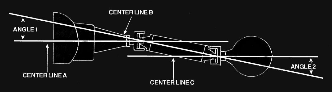
When you build a chassis and position the driveline components, you need to orient them so that the angle of a line drawn through the center of the transmission exiting through the output shaft (A) and a line drawn through the center of the driveshaft (B) is equal to but opposite the angle of a line drawn through the pinion shaft in the rear differential(C) and the line drawn through the center of the driveshaft (B).
The accompanying drawing illustrates how the lines drawn through the transmission and pinion shafts (A&C) are parallel to each other, though not in the same plane.
U-joint operating angles are generally the most common cause of driveline vibration in vehicles that have been reworked. When reworking a chassis or installing a new driveshaft in a vehicle there are basic rules that apply to U-joint operating angles that you should follow.
- U-joint operating angles at each end of the shaft should always be at least 1-degree.
If you are to achieve cancellation these U-joint operating angles on each end of a driveshaft should always be equal (within 1-degree), but opposite of each other.
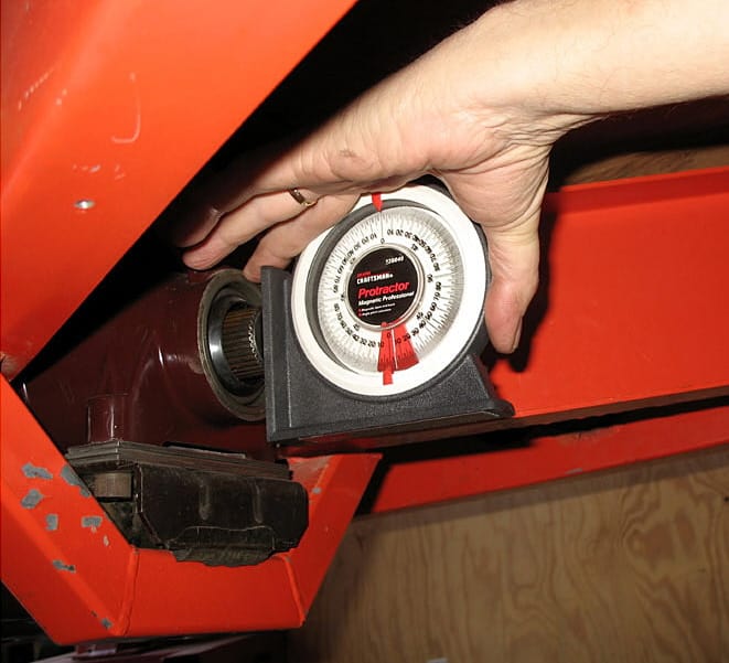
U-joint operating angles should not be larger than 3-degrees. If they are, make sure that they do not exceed the maximum recommended angles. - To set up the driveline you need to establish the angles for the transmission output shaft, rear end pinion shaft and driveshaft. A good tool for measuring these angles is an inclinometer. They can be obtained quite inexpensively from a local parts store or tool supplier.
- First measure the transmission output shaft angle. It should be pointing downward to the rear with the vehicle sitting at ride height on a level surface. At least 1-degree and ideally not more than 3-degrees down.
You can alter the transmission angle by inserting or removing shims under the rear transmission mount as shown in this photo…
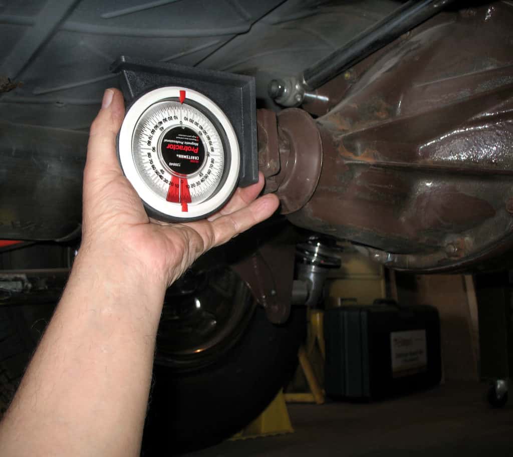
The next step is to measure the rear-end pinion shaft angle. It should be pointing upward towards the front with the vehicle sitting at ride height on a level surface.
At least 1-degree and ideally not more than 3-degrees up. You can alter the rear end pinion shaft angle by inserting or removing wedge-shaped shims under the rear spring mounts or by adjusting the length of the control arms positioning the rear end. See the photo below…
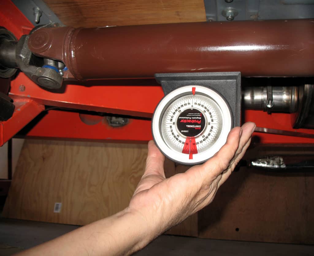
Finally measure the driveshaft angle to confirm that it is at least 1-degree down from the transmission output shaft angle and at least 1-degree up from the rear end pinion shaft angle. Achieving these angles in relation to each other will cancel out the vibration…
Checking to see if you have got it correct:
If there is no vibration under normal operating conditions then the angles are correct.
If there is vibration under acceleration, you need to add more downward pinion angle pre-load. If the opposite occurs, the vibrations tends to decrease or disappear under acceleration, you need to reduce the downward angle pre-load.
If the vibration steadily increases with driveshaft speed (either accelerating or decelerating) the symptom is primarily the result of a driveshaft imbalance or yoke run-out. Sometimes this yoke run-out problem can be improved by rotating the U-joint 180-degrees in the rear end differential yoke.
Driveshaft-related vibrations usually occur at roughly engine speed in high gear. Wheel/axle vibrations usually occur at 1/3 rd engine speed or driveshaft speed because of the differential gearing.
To determine whether it is the output of the transmission or the pinion in the differential, change gears when the noise occurs and maintain speed. If the vibration/noise changes in frequency, the source is in the transmission or engine. If the frequency remains the same it is a driveshaft problem.