GM LSx Engine Swap ~ Wiring Harness Preparation

GM LSx Swap Wiring Harness

There was a time when many hot rod enthusiasts were afraid of electronic fuel injection (EFI) on engines, preferring the “relative simplicity” of a carbureted engine that could be run in a pinch with gravity-fed fuel and no electronics. These days, fuel injection is all that comes from new vehicle factories, and EFI engine swaps into older vehicles are extremely common.

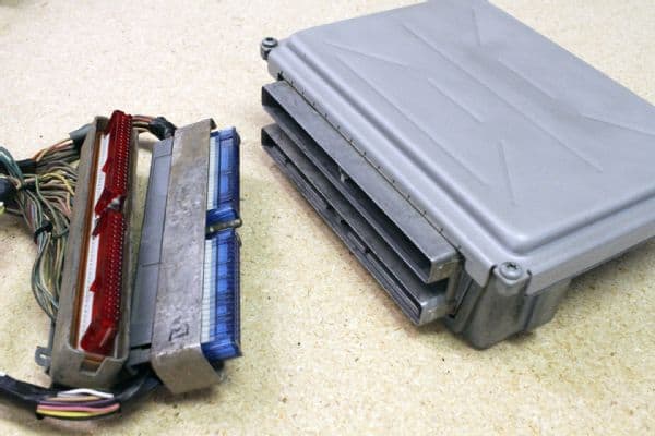
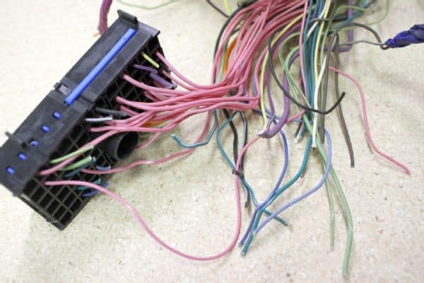
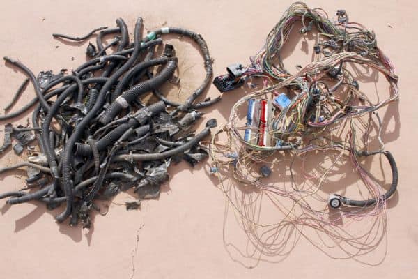
It seems for many people that the scariest part of the modern engine swap is the wiring harness.

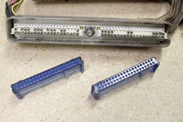
When you are doing a build with the LS family of GM engines, the idea is to end up with a simplified engine harness that only needs a minimum number of inputs/outputs for a standalone swap.

These are mainly:

  • battery voltage,
  • switched ignition voltage,
  • PCM output to control fuel pump,
  • and a brake switch signal for electronic torque converter control (if used).

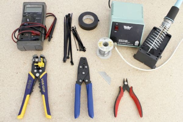
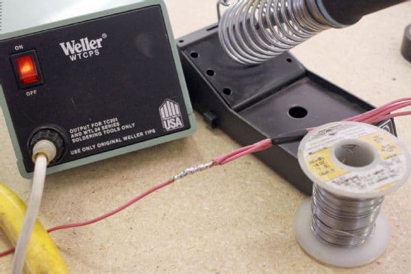
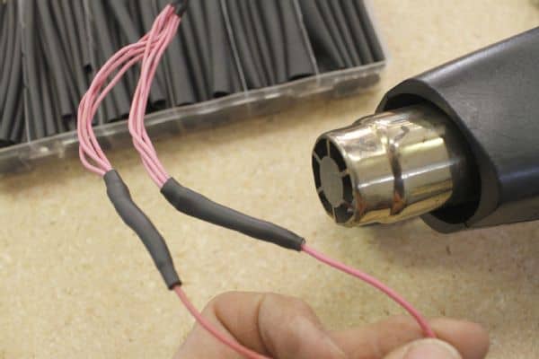
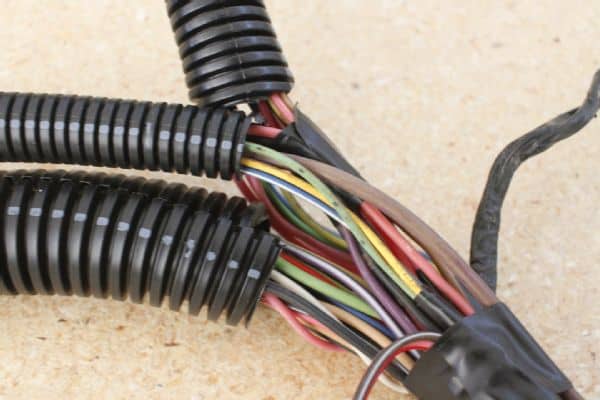
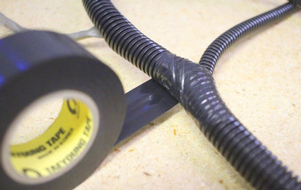
There are companies that outright sell new harnesses for LS engine swaps, and some vendors will also rework a used harness for a fee. However, with time and your attention to detail, you should be able to rework your donor harness yourself with some basic tools.

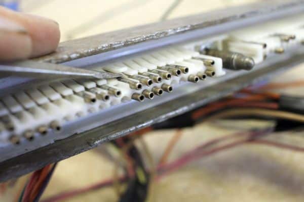
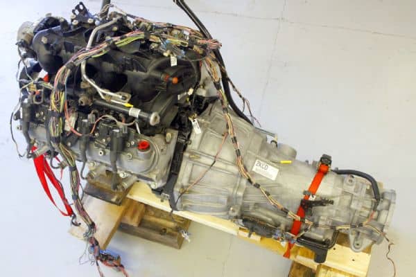
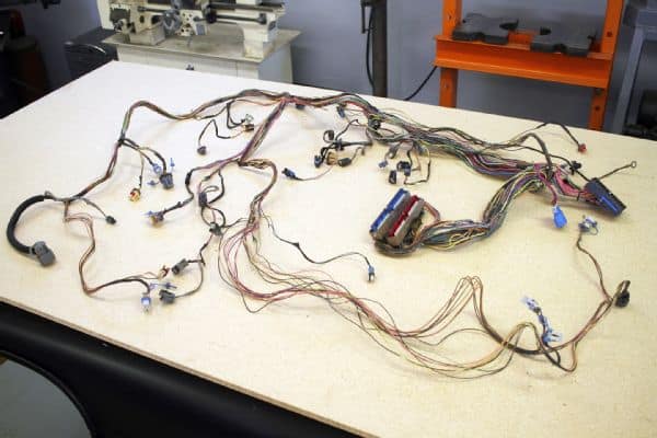
This article is meant to give you an idea what tools and techniques are involved as we show you some work from our 2002 Chevy Tahoe harness for a 5.3L engine swap. The process for other GM engine harnesses is similar.

DIY LS Engine Harness Stripped Engine Harness
Our lead image may look intimidating, but that’s actually the entire harness from our donor Tahoe. We took just the engine harness portion and started by stripping away much of the split-loom tubing and tape that covered the harness wires. Shown here is really what we are working with. You might choose to do this stripping portions at a time or all at once.

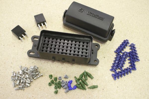
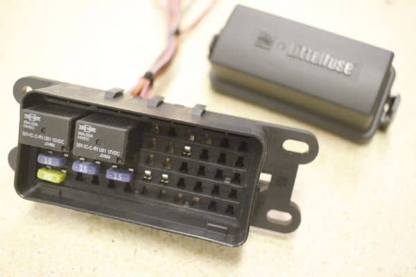
While it is possible to reuse a fuse block from the donor vehicle, they are often much larger and more complicated than necessary just to serve for this engine harness. What is needed are typically four power fuses and two relays to complete the standalone harness. Understand that this harness is just for engine control and does not necessarily tie into the rest of your vehicle harness.

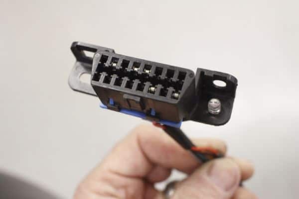
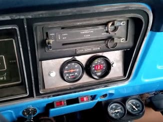
Such outputs as the speed sensor can be used to drive an aftermarket electronic speedometer and an engine rpm signal that can run a tachometer. Plus, today there are tablet apps that can read the OBD-II port data and display some gauge information.

Along with building a standalone harness for the engine swap, you will need to have the powertrain control module (PCM) reprogrammed to remove the Vehicle Anti-Theft System (VATS), accommodate a noncomputer-controlled transmission (if used), reset rear axle ratio/tire size for speedometer output, remove emissions functions or rear oxygen sensor inputs for off-road applications, set electric fan control temperatures, and so on.

DIY LS Engine Harness
We laid out the harness on a large work surface and began to familiarize ourselves with all the loom branches and connectors. Throughout the process you will want to take your time to confirm what you are keeping in the harness and what you are deleting.

The earlier LS engine models were all drive-by-cable; that is, they used a traditional mechanical throttle cable. Next came drive-by-wire (DBW) versions that use an electronic gas pedal assembly and a servo motor mounted to the throttle body that operates the throttle plate.

DBW systems on third-generation engines require you to use the gas pedal assembly and a separate throttle actuator control (TAC) module in addition to the PCM. These components must be fairly closely matched by year to work properly. In most cases, it is most reliable to use components from the same year and type vehicle.

In fact, pulling the engine and all related electronic components from a complete donor vehicle ensures that you have system-matching parts that will play well together.

Fourth-generation GM engines can have Active Fuel Management (AFM) or Displacement on Demand (DOD), which allows half the cylinders to be deactivated so the engine runs on four cylinders. These engines can be reprogrammed to disable the sometimes problematic cylinder deactivation function, leaving all factory parts in the engine.

Patten has worked with these engines and warns that if a camshaft is changed, you must ensure that the lifters, camshaft, and AFM solenoid plate all match. The wrong combination of parts can damage to the engine. Note also that fourth-generation engines do not have a TAC module and the gas pedal wires directly to the PCM.

DIY LS Engine Harness Label
By checking connectors and cross-referencing wire colors with wiring diagrams, we labeled all the connectors to make further work easier. In general, pink wires at sensors are 12V power lines and black wires are ground. Some connectors may appear very similar but are mechanically keyed differently.

There was also a flex-fuel version (L59) of the 5.3L V-8. This engine used different fuel injectors and pump to flow more fuel. In addition, the PCM uses program code to read a fuel composition sensor that provides a digital pulsed signal based on the amount of ethanol in the fuel supply. This function can be turned off in the programming and the engine run on normal (non-E85) gasoline without having to change any parts.

Of particular interest to those doing a harness swap for a 4WD rig is dealing with the vehicle speed sensor (VSS). The PCM reads the speed of the vehicle to determine transmission shifting points. When using a computer-controlled transmission, such as a 4L60E or 4L80E automatic, you will need the VSS to properly shift the transmission. GM places the VSS at the output of the T-case on 4WD models but combines this configuration with the use of a low-range indication switch wired to the PCM.

If you use a VSS in this location, you will want to provide this high/low range input to the PCM and keep the capability with a 4WD PCM tune. Another option is to use an aftermarket kit to place the VSS between the transmission and transfer case. In this scenario, you can use a 2WD PCM tune because high/low range indication is not needed. You can find more specific information about VSS function for other drive-train configurations on lt1swap.com.

DIY LS Engine Harness Tools
There are a few basic tools you will probably want to have: wire cutters and strippers, terminal crimpers, soldering iron, heat gun, and multimeter to check continuity within the harness. Zip-ties and tape are handy for organizing your wiring branches as you work.
DIY LS Engine Harness PCM Connectors
Here is the PCM and its harness connectors. You will want to disconnect the harness from the PCM before performing any work on the harness. You will find helpful tutorials and wiring diagrams on lt1swap.com to guide you through the harness rework.
DIY LS Engine Harness Fuse Block Cutting
To begin the harness rework, the main fuse block connector and several other harness connectors are cut free, leaving the engine harness wires to work with. Unneeded wires are simply followed back through the harness and deleted. Pink power supply wires cut from this fuse block will be routed to the new standalone fuse block.
DIY LS Engine Harness PCM Connector Covers
Protective plastic covers are removed from the two large PCM connectors to allow access to the connector pins. Some pins will be removed and a few may be added, depending on your application.
DIY LS Engine Harness PCM Connector Pins
Some wires to be deleted are unpinned from the PCM connector, then the pin and wiring removed. The connectors on this PCM have small numbers to label each of the 80 pins in four banks of 20 pins.
DIY LS Engine Harness Power Wire Splicing
Various power wires for injectors, O2 sensors, PCM, and others are combined into three voltage wires to be run to the fuse block. Mid-harness splices should be made by mechanically overlapping and twisting wires together followed by soldering the connection.
DIY LS Engine Harness Heat Shrink Tubing
Adhesive-lined heat shrink tubing can be used to cover the spliced sections. The object here is to make reliable, weather-sealed connections that won’t cause any headaches in the future.
DIY LS Engine Harness Fuse Block
A lot of harness builders use a simple, open four-fuse block for the harness, and that works fine to provide a fuse for constant 12V and three for switched 12V sources to the various components. We wanted something that was waterproof for underhood use and provided extra room for additional fuses and relays. We used a Littelfuse HWB60 power distribution module.
DIY LS Engine Harness Fuse Block
The HWB60 meets IP67 weatherproofing specs. Wires plug into the back of the module using industry-standard Delphi Metri-Pack Series 280 tanged terminals. Here is our fuse box setup with the fuses and relays. It gets capped with a gasketed cover. You will also end up with a handful of wires to be integrated into your gauges or other vehicle wiring. These include tach output and speed output, among others.
DIY LS Engine Harness DLC Connector
You will need an OBD-II Data Link Connector to read codes and PCM data from the system. You can pull the one from the interior harness of your donor vehicle or purchase one individually from an electronics supply house. In either case, you will need to wire it into the harness with 12V power, data, and ground connections. A check engine light is added by running 12V power and the malfunction indicator light (MIL) wire from the PCM to your own light bulb or LED.
DIY LS Engine Harness Layout
You can preserve the layout of all the harness branches as they were in the donor vehicle or make some routing and length changes as needed for your application. We laid our harness back on our donor engine and transmission to finalize the routing before we finished taping the branches in place.
DIY LS Engine Harness Split Loom
Once we were satisfied with the final layout (and a possible engine test start), the harness was repackaged in split-loom tubing. We purchased high-temp loom rated to 300 degrees F to withstand the underhood heat.
DIY LS Engine Harness Taping
We wrapped the harness branch junctions with nonadhesive, high-temp vinyl tape to completely cover all the individual wires. Resist using electrical or most other adhesive tapes, as they’ll eventually turn gooey over time with underhood heat.

By Jay Kopycinski